- 您现在的位置:买卖IC网 > Sheet目录314 > ATSTK600 (Atmel)DEV KIT FOR AVR/AVR32
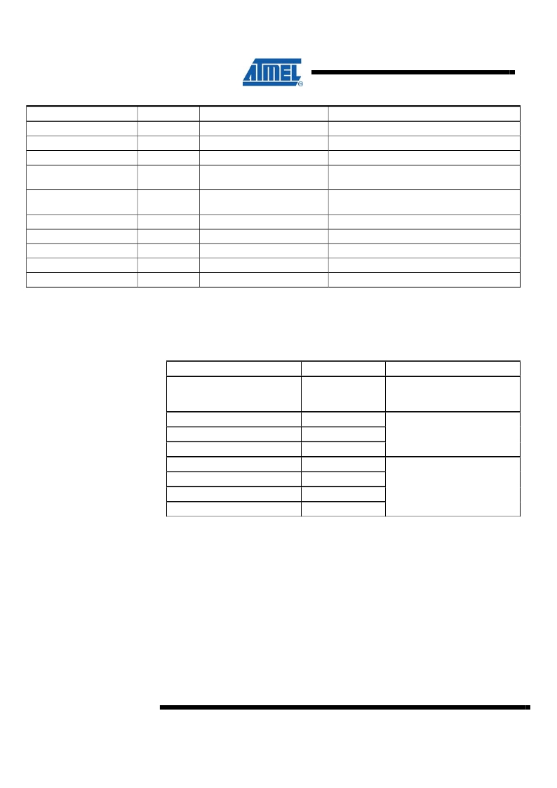
Table 4-7. Command format.
Field
Command ID
NumBytes
mode
delay
Size
1 byte
2 byte
1 byte
1 byte
Values
CMD_PROGRAM_FLASH_ISP
XML: mode *
XML: delay
Description
Command id
Total number of bytes to program, MSB first
Mode byte*
Delay, used for different types of programming
termination, according to mode byte
cmd1
cmd2
cmd3
1 byte
1 byte
1 byte
Command 1 (Load Page, Write Program
Memory)
Command 2 (Write Program Memory Page)
Command 3 (Read Program Memory)
poll1
poll2
Data
1 byte
1 byte
N bytes
XML: pollVal1
XML: pollVal2
Poll Value #1
Poll Value #2 (not used for flash programming)
N data
Mode byte
The mode parameter is essential for how this command works. The bits in the mode
byte have the following meanings:
Table 4-8. Mode byte, bit descriptions.
Bit #
0
1
2
3
4
5
6
7
Description
Word/Page Mode
(0 = word, 1 =
page)
Timed delay
Value polling
RDY/BSY polling
Timed delay
Value polling
RDY/BSY polling
Write page
Mode
Word Mode
Page Mode
The Word/Page Mode bit selects if the device supports page programming or not.
The command bytes are different for word and page mode. In word mode, the ISP
commands Write Program Memory and Read Program Memory are used. In page
mode, Load Page , Write Program Memory Page and Read Program Memory are
used. The read instruction is used if Value Polling is specified in the mode bit. The
Low/High byte selection bit (3 rd bit in the Load Page, Write Program Memory
commands) is handled by STK600, so leave this bit cleared. The instruction values
are found in the SPI Serial Programming Instruction Set found in the device
datasheet.
According to the mode, different termination methods are selected – Timed delay ,
Value polling or RDY/BSY polling .
For paged operation, the Write page bit decides if a Write Program Memory Page
command should be issued after the data has been loaded into the page buffer. For
10
AVR079
8133A-AVR-04/08
发布紧急采购,3分钟左右您将得到回复。
相关PDF资料
ATXMEGAB1-XPLD
KIT EVAL FOR ATXMEGAB1
AUIR2085S
IC DVR HALF-BRDG SELF OSC 8SOIC
AUIRS2003S
IC DRVIER HALF-BRIDGE 8SOIC
AUIRS2004S
IC DRVIER HALF-BRIDGE 8SOIC
AUIRS2112S
IC DRIVER HIGH/LOW SIDE 16SOIC
AUIRS2113S
IC DRIVER HIGH/LOW SIDE 16SOIC
AUIRS2118S
IC DRIVER HIGH SIDE SGL 8SOIC
AUIRS2123S
IC DRIVER HIGH SIDE 600V 8SOIC
相关代理商/技术参数
ATSTK600-ATMEGA2560
功能描述:插座和适配器 STK600 DEVICECARD ATMEGA2560 RoHS:否 制造商:Silicon Labs 产品:Adapter 用于:EM35x
ATSTK600-ATTINY10
功能描述:插座和适配器 STK600 adaptercard for ATtiny10 RoHS:否 制造商:Silicon Labs 产品:Adapter 用于:EM35x
ATSTK600-DIP40
功能描述:插座和适配器 SOCKET ADAPTER CARD FOR ATSTK600 RoHS:否 制造商:Silicon Labs 产品:Adapter 用于:EM35x
ATSTK600-LCD160
功能描述:子卡和OEM板 STK600 LCD EXTENSION CARD FOR megaAVR RoHS:否 制造商:BeagleBoard by CircuitCo 产品:BeagleBone LCD4 Boards 用于:BeagleBone - BB-Bone - Open Source Development Kit
ATSTK600-LCDX
功能描述:子卡和OEM板 STK600 LCD FOR XMEGAB RoHS:否 制造商:BeagleBoard by CircuitCo 产品:BeagleBone LCD4 Boards 用于:BeagleBone - BB-Bone - Open Source Development Kit
ATSTK600-RC01
功能描述:插座和适配器 STK600 ROUTINGCARD RC020T-1 RoHS:否 制造商:Silicon Labs 产品:Adapter 用于:EM35x
ATSTK600-RC02
功能描述:插座和适配器 STK600 ROUTINGCARD RC008T-2 RoHS:否 制造商:Silicon Labs 产品:Adapter 用于:EM35x
ATSTK600-RC03
功能描述:插座和适配器 STK600 ROUTINGCARD PDIP28 RoHS:否 制造商:Silicon Labs 产品:Adapter 用于:EM35x
